Safety Relief Valves (SRV) for Critical Overpressure Protection
Key features:
Use of Bar stock trims & qualified castings
Certified engineered quality springs are used
Seat options: Metal to metal, soft seat
Pressure can be set as per requirement
Hard facing for high temperature & pressure
Replaceable seats & parts
Pressure rating: 150# to 2500# (with table-H & E options)
Explore our high-performance Spring-Loaded and Pilot-Operated safety valves designed to protect your equipment.
📞 Call / WhatsApp:
+91-8652075992, +91-9967552335
✉️ Email:
sales@hubluxe.com, info@hubluxe.com
At Hubluxe Engineering, safety is non-negotiable. Hubluxe Safety Relief Valves (SRV) are precision engineered to protect boilers, pressure vessels or compressors. Our Safety valves are designed for instant pressure reliefs when system limits are exceeded.
Hubluxe offers both Spring Loaded Safety Relief Valves & Pilot Operated Safety Relief Valves models to suit your critical process needs. Our valves are engineered to meet API 520 / API 526 / API 527, ASME BPVC, and ASME B16.5 / B16.34 standards.
Hubluxe Engineering’s Safety Relief Valves (SRV) are engineered for zero-compromise protection. Compliant with API 520 and API 526, our spring-loaded design ensures rapid opening at set pressure and precise blowdown for a tight reseal, protecting your boilers, vessels, and pipelines from overpressure events.
Safety Relief Valves technical specifications:
- Design standards:
As per standards API-520 / API-526 / API-527
- Boiler & Pressure Vessel code:
ASME BPVC section VII division I
- Standards
as per ASME B 16.5& ASME B 16.34
- Pressure Rating:
150# to 2500# with drilling options in Table-H & Table E
Our SRVs are rigorously tested for set pressure accuracy and seat tightness. Designed for Steam, Gas, and Liquid service, they meet the stringent requirements of ASME Section VIII and API 526 for capacity and dimension.
Key applications of Safety Relief Valves: Their role is to protect the equipment by releasing excess pressure and are used in:
- Steam boilers & turbines
- Process Vessels
- Oil & Gas Pipelines
- Chemical reactors
- Thermal relief in pipelines
- Power Generation plant
The Primary Role of Pressure Reducing Valves (PRVs) is to lower a high upstream pressure to a safe, steady downstream level.
- Hydropower systems
- Oil & Gas industries
- Energy & Power
- Chemical Processing
- HVAC systems
- Desalination plants
- Process control
- Filtering stations
- Flow limiters
Pressure Regulating valve’s role is to maintain stable pressure levels despite irregular fluctuations in flow or upstream conditions. Here are some key applications of PRVs where they are used:
- Steam boilers & turbines
- Steam supply
- Chemical productions
- Hydraulic systems
- Pneumatic systems
- Oil & gas industry
- Medical equipment
- Potable water systems
- Gas systems
Hubluxe make Safety relief valves, Pressure regulating valve & Pressure reducing valve details along with model numbers:
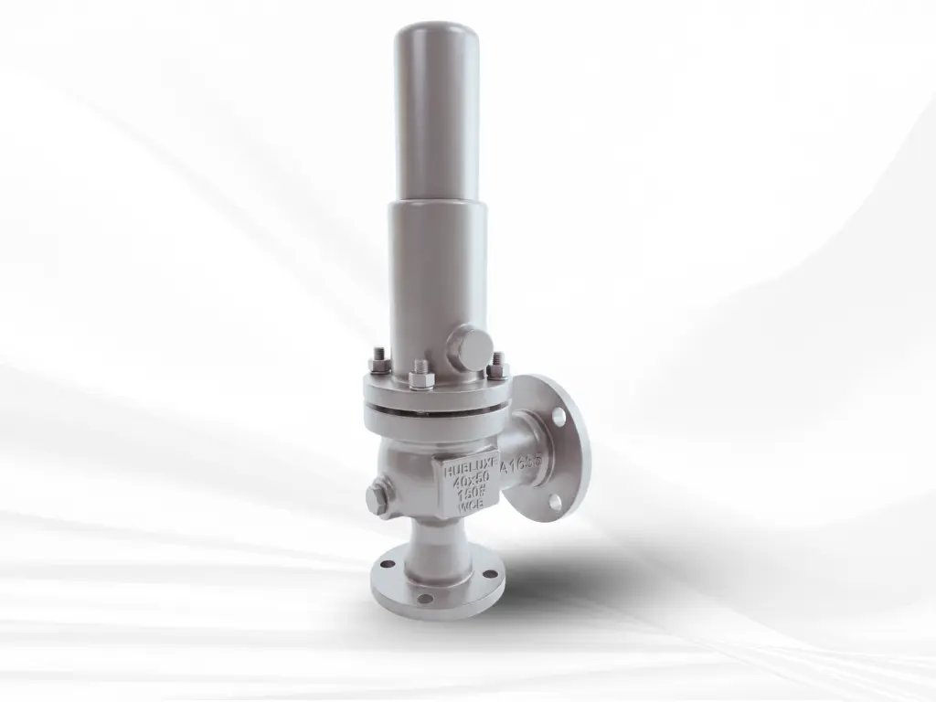
Model: HE60-O & HE60-C
Design Features:
- Use of Bar stock trims & qualified castings
- Certified engineered quality springs are used
- Seat options: Metal to metal, soft seat
- Pressure can be set as per requirement
- Hard facing for high temperature & pressure
- Replaceable seats & parts
- Pressure rating: 150# to 2500# (with table-H & E options)
Technical Features:
- Size: 25 mm x 50 mm to 250 mm x 350 mm (1”x2” to 10”x14”) – higher sizes on request
- Certified engineered quality springs are used
- Seat options: Metal to metal, soft seat
- Pressure can be set as per requirement
- Hard facing for high temperature & pressure
- Replaceable seats & parts
- Pressure rating: 150# to 2500# (with table-H & E options)
📞 Call / WhatsApp:
+91-8652075992, +91-9967552335
✉️ Email:
sales@hubluxe.com, info@hubluxe.com
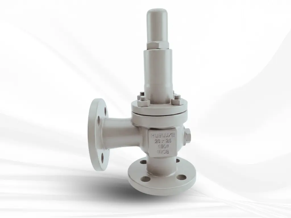
Model: HE21-O & HE21-C
Design Features:
- Use of Bar stock trims & qualified castings
- Certified engineered quality springs are used
- Seat options: Metal to metal, soft seat
- Pressure can be set as per requirement
- Hard facing for high temperature & pressure
- Replaceable seats & parts
- Pressure rating: 150# to 2500# (with table-H & E options)
Technical Features:
- Size: 15 mm x 25 mm to 50 mm x 50 mm (1/2”x1” to 2”x2”) – higher sizes on request
- Standards as per ASME B 16.5& ASME B 16.34
- End connection: Flange end
- Pressure Rating: 150# to 2500# with drilling options in Table-H & Table E
📞 Call / WhatsApp:
+91-8652075992, +91-9967552335
✉️ Email:
sales@hubluxe.com, info@hubluxe.com
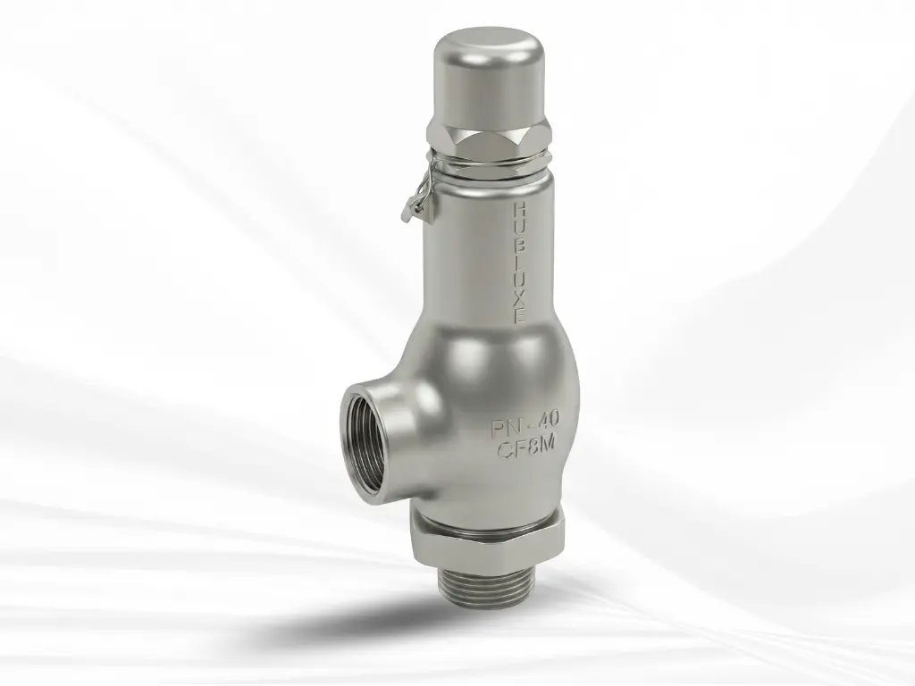
Model: HE20-O & HE20-C
Design Features:
- Use of Bar stock trims & qualified castings
- Certified engineered quality springs are used
- Seat options: Metal to metal, soft seat
- Pressure can be set as per requirement
- Hard facing for high temperature & pressure
- Replaceable seats & parts
- Pressure rating: 150# to 2500# (with table-H & E options)
Technical Features:
- Size: 15 mm x 25 mm to 50 mm x 50 mm (1/2”x1” to 2”x2”) – higher sizes on request
- End connection: Threaded (Screwed end) as per ASME B1.20.1 & is available in BSP, BSPT, NPT
📞 Call / WhatsApp:
+91-8652075992, +91-9967552335
✉️ Email:
sales@hubluxe.com, info@hubluxe.com
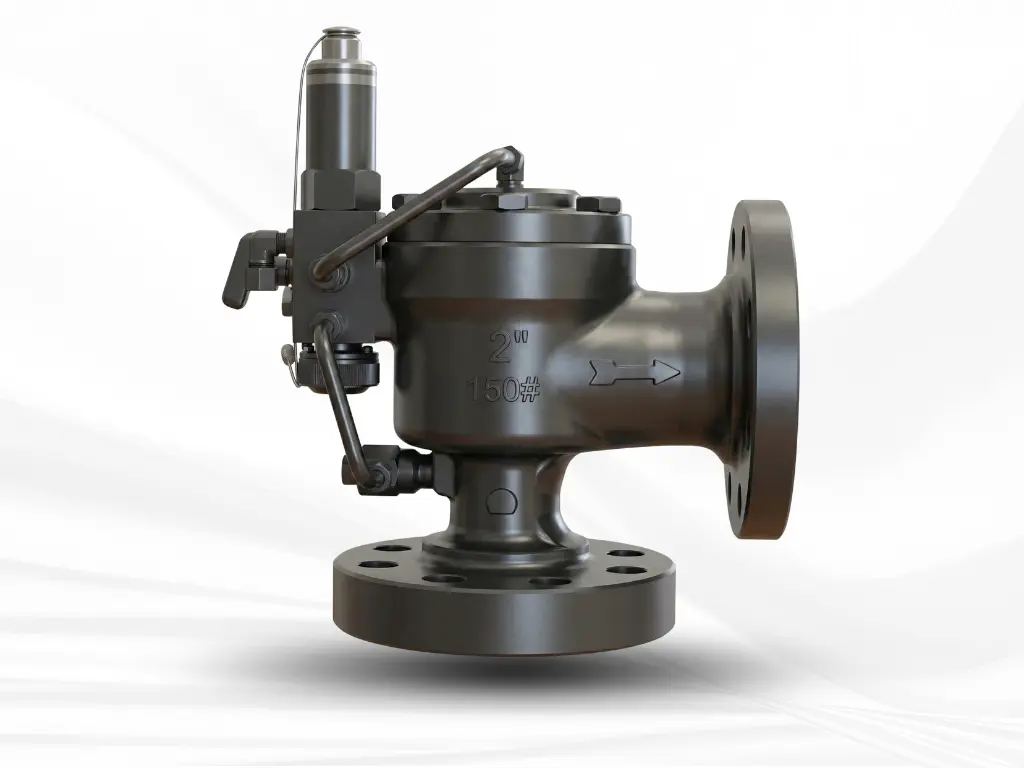
Model: HE60-PO
Design Features:
- Angle pattern with pilot operated valve
- Pop type Full Lift design
- Less blowdown-keeping the system more stable & efficient
- Replaceable seats & parts
- Seat options: Metal to metal, soft seat
- Hard facing for high temperature & pressure
- Use of Bar stock trims & qualified castings
- Certified engineered quality springs are used
Technical Features:
- Size: 25 mm x 50 mm to 250 mm x 350 mm (1”x2” to 10”x14”) – higher sizes on request
- Design standards: As per standards API-520 / API-526 / API-527
- Standards as per ASME B 16.5 & ASME B 16.34
- Pressure Rating: 150# to 2500# with drilling options in Table “H” & Table “E”
📞 Call / WhatsApp:
+91-8652075992, +91-9967552335
✉️ Email:
sales@hubluxe.com, info@hubluxe.com
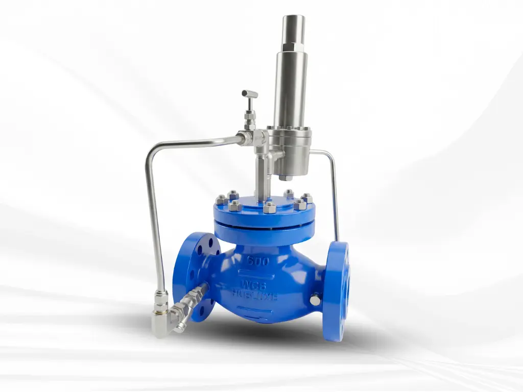
Model: HELPRV-201
Design Features:
- Self-operating pressure reducing valve for general industrial applications across air, gas & liquid services
- Maintains constant outlet pressure regardless of variations in inlet pressure or flow
- Optional stainless-steel diaphragm for high temperature services
- Use of soft sealing discs suited for various fluids, ensuring compatibility across wide pressure & temperature range (up to 1900 C)
- Featuring built in safety mechanism against high inlet pressure
- Well suited for low pressure settings below 1500 mmWC (0.15 Barg)
- It is best for sensitive applications due to its capability of controlling downstream pressure as low as 15mmWC
Technical Features:
- Size: 15 mm to 150 mm (½” to 6”)
- Pressure rating: ANSI 150# to 300#
- Maximum Inlet Pressure: 5 to 350 psig
- Maximum Outlet Pressure: 10mmWC to 150 psig
- Temperature Range: -40 °C to 350 ° deg. C
- Applicable Media: Air, gas, and liquids
- Material Options: WCB, WC6, WC9, LCB, LCC, CF8, CF8M, CF3, CF3M, CF8C
📞 Call / WhatsApp:
+91-8652075992, +91-9967552335
✉️ Email:
sales@hubluxe.com, info@hubluxe.com
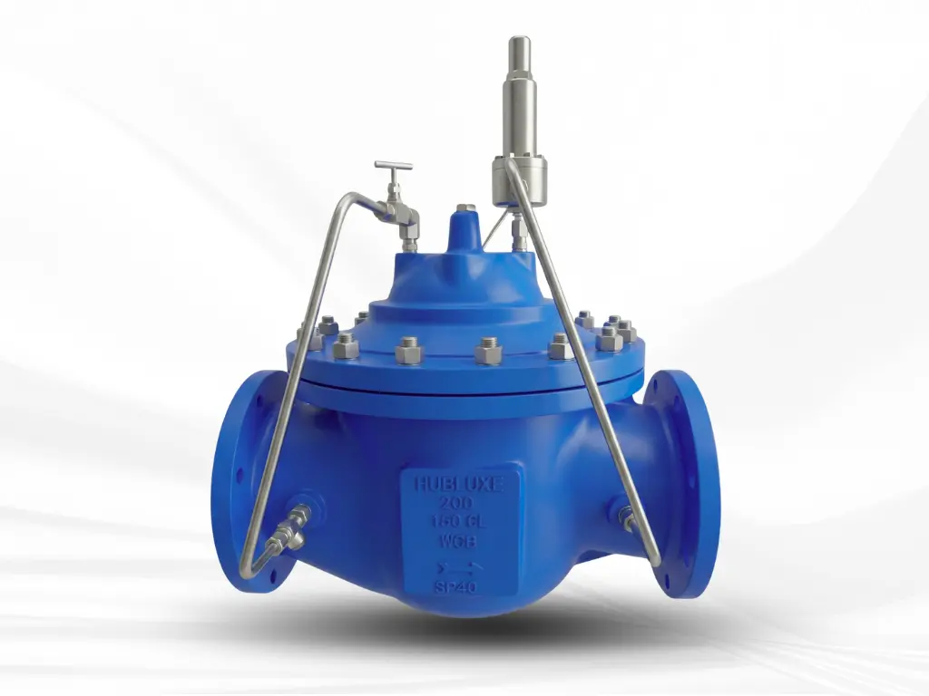
Model: HE-261
Design Features:
- Dual installation flexibility: In Main line – prevents upstream pressure from dropping below preset value Bypass Line: Release excess pressure into sump or bypass, protecting the downstream equipment
- Remotely operated: Can be operated remotely to re-circulate the full flow, enhancing the system control
- Pump protection: perfect for pump bypass application, safeguarding downstream equipment from overpressure
- Smart pilot control: Relief pilot (F-16) remains closed under spring tension; and opens automatically when upstream pressure exceeds set value, ensuring full valve opening instantly
- Excellent & reliable performance: Self acting design ensures automatic protection without external energy resources
Technical Features:
- Size: 25 mm to 600 mm (½” to 24”) – Flange ends
- Pressure rating: ANSI 150# & 300#
- Set Pressure: 1 to 300 psig
- Adjustment range: 0 to 150 psig
- Temperature Range: -40 °C to 120 ° deg. C
- Applicable Media: Any Liquid service
- Material Options: WCB, WC6, WC9, LCB, LCC, LC3, C5, C12, CF8, CF8M, CF3, CF3M
📞 Call / WhatsApp:
+91-8652075992, +91-9967552335
✉️ Email:
sales@hubluxe.com, info@hubluxe.com
FAQs (Frequently asked questions)
Find detailed answers to common questions about Safety Relief Valves in our Knowledge centre.
Safety Relief Valves works automatically when following conditions trigger:
- Normal state: When the system is working within the Safe Pressure Limits, the valve stays in CLOSED position
- Overpressure condition: The valve OPENS automatically if the pressure rises above the set pressure limits
- Pressure Release: The excess pressure is discharged safely into the environment
- CLOSED state: Once the excess pressure is released the safety valve returns to its normal position i.e. CLOSED.